Ceramic AM gives designers freedom, but it is not a free-form process. The green body is weak, the binder has to leave, and unsupported surfaces sag. A few DFM rules separate parts that print reliably from parts that fail in the oven.
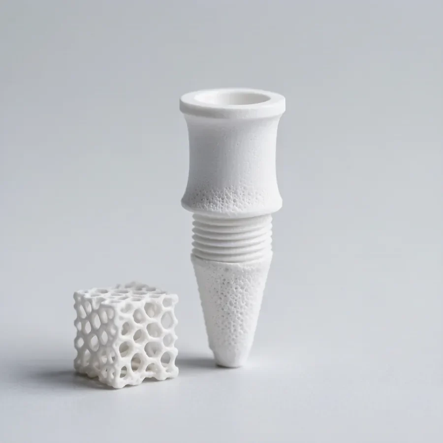
Minimum walls and holes
Our process can resolve features down to roughly the 40 µm pixel size in the XY plane, but that does not mean a 40 µm wall will survive debinding and sintering. We recommend a minimum wall thickness of 100 µm as-sintered, with 200 µm or more preferred for structural features. Pins, fins and posts that are tall and thin need even more section or a supported base to avoid warping under their own weight during the green stage.
Holes and channels follow similar rules. Through-holes down to 0.5 mm are possible, but blind holes need venting or should be opened to the outside. Long narrow channels trap binder vapour; keeping diameter above 1 mm or providing multiple exits dramatically improves yield.
Supports and orientation
Overhangs and bridges in LCM need support from the surrounding resin during printing, but unlike metal powder-bed fusion, the support material is the same resin as the part. This means every support contact point leaves a witness mark. We design supports to attach to non-critical surfaces and thin walls to avoid thick contact patches.
Orientation matters. Flat, broad surfaces parallel to the build platform tend to have the best surface finish. Tall, slender parts are usually oriented to reduce Z-height, because the Z direction is where layer lines and shrinkage anisotropy are most visible. We pick orientations that balance surface quality, support accessibility and dimensional accuracy.
Avoiding enclosed voids and stress concentrators
Enclosed voids are the biggest avoidable risk. Any cavity that is sealed during printing becomes a sealed pressure vessel during debind. If the geometry needs a hollow region, provide at least one opening for gas escape. Alternatively, design the part as an assembly of two shells that are bonded after sintering.
Sharp internal corners and sudden section changes create stress concentration during shrinkage. Filleting inside corners and blending wall-thickness transitions reduce crack initiation. Draft angles are not required for LCM, but they help when a part is later moulded or pressed as a secondary operation.
Surface finish and post-processing allowance
Surface finish on downward-facing surfaces is usually rougher than top surfaces because of support contact. If a mating surface or sealing surface needs to be smooth, orient that face upward or add 0.2 to 0.5 mm of grinding stock. As-sintered Ra of 0.3 to 0.9 µm is acceptable for many applications, but sealing interfaces and optical bores usually need post-machining.
We return a design-for-manufacturing note with every quote. The note flags features that are at risk and suggests geometry changes. A small radius here or an open vent there often turns a borderline part into a reliable one.