Lithography-based Ceramic Manufacturing (LCM) is the bridge between a CAD file and a fully dense alumina or zirconia component. The printed green part is only the beginning; the real work happens in the debind and sinter ovens.
What LCM actually is
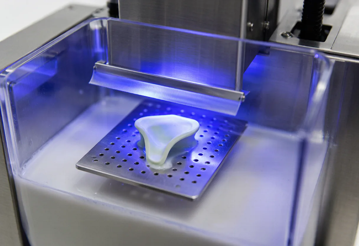
LCM is a vat-photopolymerisation process. A ceramic powder, typically alumina, zirconia or silica, is suspended in a photosensitive resin at a solids loading of 35 to 60 percent by volume. A digital light projector flashes a 460 nm image of each slice onto the bottom of a resin vat. Where the light hits, the resin cross-links and the ceramic particles are locked into a green layer. The build platform lifts, a new layer of resin flows in, and the process repeats.
The key difference from plastic vat photopolymerisation is that the green body is roughly 40 to 55 percent ceramic by volume. The rest is organic binder and monomer. Those organics must leave before the part can be fired, which is why the post-print steps are longer and more critical than the print itself.
The light engine and pixel size
Our systems use a 460 nm LED engine with a 40 µm pixel pitch. That pixel size sets the finest detail we can resolve on the green part, so a wall that is only one or two pixels wide in the CAD file may not survive debinding. Layer thickness is selectable from 10 µm to 100 µm. For most engineering parts we run 25 µm, which gives a smooth surface finish without extending build time unnecessarily.
The light engine does not draw each line like a laser; it projects the entire slice at once. This makes build speed independent of part complexity in the XY plane. A dense lattice and a solid cube of the same footprint take the same exposure time. The practical limit is the amount of ceramic that can be suspended in the resin while still allowing fresh resin to reflow between layers.
Debinding: the make-or-break stage
After printing, the green part is washed to remove uncured resin and then placed in a debind furnace. Debinding runs from roughly 100 °C to 600 °C and can take many hours. The binder breaks down and exits as gas; if the temperature ramps too fast, the gas pressure can blister or crack the part. We use ramp rates between 2 °C and 5 °C per minute, depending on wall thickness and cross-section.
Channel geometry matters during debind. Blind holes, enclosed cavities and long narrow channels can trap decomposition products. Designers should provide venting paths or avoid fully enclosed voids. This is the same reason that hollow turbine blades need an open leaching path for silica cores.
Sintering and shrinkage compensation
Once the binder is gone, the brown body is fragile and porous. Sintering heats it to 1300 °C to 1800 °C, depending on the material. During this stage, ceramic particles bond and the part densifies. Alumina reaches its target density at a different temperature than zirconia, and our silica-based CoreCera SC grade is engineered to sinter just enough to hold shape while remaining leachable.
The linear shrinkage is typically 15 to 20 percent. We compensate by uniformly scaling the CAD file before slicing. Because shrinkage is isotropic when the print and sinter process are well controlled, a 20 percent linear scale-up produces a part that lands within our ±40 µm tolerance band after firing.
Verification and quality gates
We verify every batch with digital calipers, density measurements and visual inspection under magnification. Finished density reaches 99.4 percent of theoretical for alumina and zirconia grades. As-sintered surface roughness is in the 0.3 to 0.9 µm Ra range. If a customer needs a finer finish or tighter tolerance, we can diamond grind critical surfaces after sintering.